Building a TENS device from scratch & scraps
Building a Monophasic TENS Device for the Hand
I’ve always been fascinated by the intersection of electronics and the human body —how a few carefully shaped pulses can interact with nerves and muscles. Recently, I built a monophasic TENS (Transcutaneous Electrical Nerve Stimulation) device for a family member, specifically tailored for the hand.
🔋 Power Stage
The heart of any stimulator is its power supply. I started with a 3.7V LiPo battery as the energy source, managed by the MCP73831 charger IC. This gave me a simple USB-C charging interface and safe single-cell management.
From there, I needed two rails:
- +3.3V logic rail for the microcontroller and digital circuitry
- High-voltage rail (~32V) for the stimulation pulses
The TPS55340 boost converter handled the heavy lifting, stepping the battery voltage up to 32V. Careful selection of inductors (100 µH for the boost stage).
While the boost converter gave me the high-voltage stimulation rail, the digital brain needed a clean and stable 3.3V supply. For that, I used the TPS63001 buck‑boost converter from TI.
Why this choice?
- The hand‑held device runs from a single Li-ion cell, which can swing from 4.2V (fully charged) down to ~3.0V (discharged).
- A simple LDO wouldn’t cut it, because once the battery dips below 3.3V, the logic rail would collapse.
- The TPS63001 solves this by buck‑boosting: it can step voltage up or down as needed, keeping the microcontroller happy at 3.3V across the entire discharge curve.
This ensured the ATmega32U4 and other logic devices always had a reliable rail, independent of battery state.
Control Stage
For brains, I went with the ATmega32U4. It’s a familiar workhorse, USB-capable, and has enough timers and PWM channels to generate the stimulation waveforms.
Key features in the control block:
- 10bit PWM outputs mapped to finger electrodes (Thumb, Index, Middle, Ring, Pinky)
- ADC inputs reserved for sensing or feedback (though not strictly necessary in monophasic mode)
- Internal clock for stable timing
- Reset and ISP header (TC2030) for easy firmware flashing
I wrote firmware to generate monophasic pulses with adjustable frequency and duty cycle. The microcontroller essentially acts as a programmable waveform generator, with parameters tuned for therapeutic comfort.
Output Stage
The output stage is where the magic happens. Here, the boosted 32V rail is gated by N-Channel MOSFET (DMN6075S) controlled by the MCU and BJTs (FZT853, MMBT2222) to deliver a limited controlled current. Inspired by this: https://electronics.stackexchange.com/questions/288388/help-dimensioning-resistors-in-a-two-npn-transistor-current-limiter-circuit
Each electrode channel is tied to a finger pad, with the palm serving as a common ground. The design ensures that current flows in a monophasic fashion—one direction only—avoiding the complexity of biphasic balancing but still effective for localized stimulation.
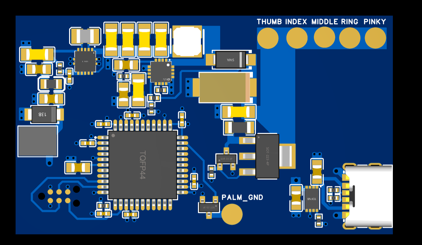
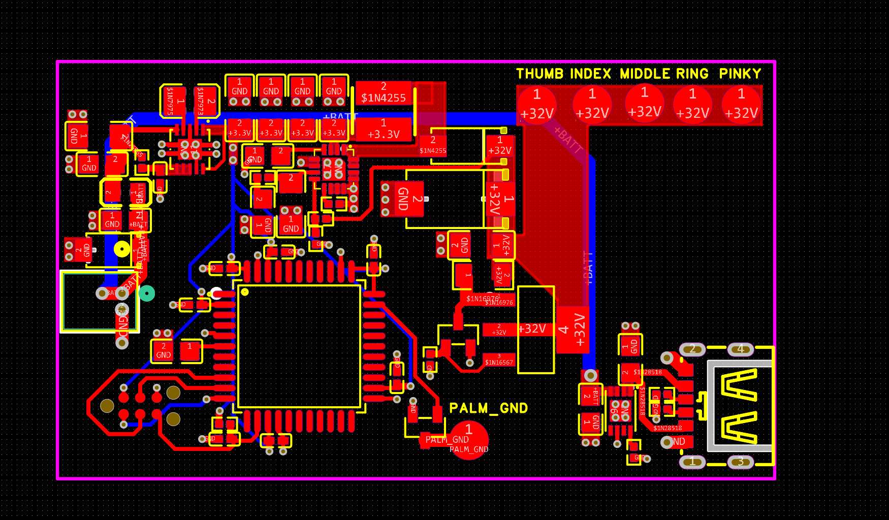
Electrode Layout
The electrodes were arranged to match the hand anatomy:
- Thumb, Index, Middle, Ring, Pinky each get their own channel, which are “on”
- Palm is the common ground reference, which gets switched via the MOSFET and the MCU at a certain frequency, e.g. 14Hz.
This layout allows selective stimulation of different fingers, useful for rehabilitation exercises.
🧩 Putting It All Together
So the blocks look like this:
| Block | Key Components | Function |
|---|---|---|
| Power | MCP73831, TPS55340, TPS63001 | Battery charging, boost to 32V, 3.3V rail |
| Control | ATmega32U4, crystal, ISP header | Generate PWM pulses, manage timing |
| Output | MOSFETs, BJTs, TVS diodes | Gate high-voltage pulses to electrodes |
| Electrodes | Finger pads + palm ground | Deliver stimulation to hand muscles |
Reflections
This project was equal parts electronics design and human-centered engineering. The monophasic approach kept things simple, and by breaking the design into clear blocks—power, control, output— I could iterate quickly.
Most importantly, it’s not just a gadget. Total cost for the project is < $100.